


Understanding Network TAPs – The First Step to Visibility
Introduction
A network TAP (Test Access Point) is a simple device that connects directly to the cabling infrastructure to split or copy packets for use in analysis, security or general network management. Although the term “Tap” predates the networking industry by decades, the IT industry has generally adopted the term to mean Test Access Point.
Network TAPs Overview
Since a network TAP provides the most effective means to copy actual traffic running across a system, the remainder of this paper is dedicated to TAP types, usage and functionality. It should be noted that TAPs are available for a wide variety of network speeds and cable types. Instead of two switches or routers connecting directly to each other, the network TAP sits between the two endpoint devices connected directly to each of them. Then traffic is seen and copied, providing visibility into the networked traffic. See Figure 1.
TAPs are straightforward devices that run for years and are generally placed in secured locations. Once the traffic is tapped, the copy can be used for any sort of monitoring, security, or analytical use. Thus, TAPs are a key component of any visibility system.
 Figure 1: Direct cabling vs. TAP cabling
Types of Network TAPs and How They Work
There are many different types of TAPs. The two primary types of network TAPs are Passive TAPs and Active TAPs.
Passive TAPs
A passive TAP requires no power of its own and does not actively interact with other components of the network. It uses an optical splitter to create a copy of the signal and is sometimes referred to as a “photonic” TAP. Most passive TAPs have no moving parts, are highly reliable and do not require configuration.
A Typical TAP Installation Involves:
- Placing the TAP on a shelf or in a rack
- Connecting the cables
- Verifying everything is working
It is really that simple. If the TAP fails to work, there is probably a cabling issue or a bad connection. Do be aware that installing or replacing a TAP in an existing environment does bring down the link while the cables are reconnected. So TAP installations are typically scheduled during pre-defined maintenance windows, or during the network architecture design phase, prior to running live traffic.
Optical fiber sends light from a transceiver through a thin glass cable to a receiver on the other end. Instead of connecting directly to each other, each of the two endpoint nodes (switches, routers, database, etc) are connected to network ports on the TAP. These special ports are physically wired in pairs such that traffic continually passes through them. In addition to the network ports are monitoring ports. The monitoring ports send out complete copies of the traffic seen, as shown in Figure 2.
 Figure 2: TAP diagram showing logical flow
Unlike network ports with both TX (transmit) and RX (receive) traffic, monitoring ports are unidirectional and only send traffic. They have no ability to receive traffic and never pass traffic back into the system. You will notice there are two monitoring ports in the diagram. Since each network port both sends and receives traffic, a 10Gb link could have 20Gb running across it. If all this traffic were put into one monitor cable, the link could quickly be oversubscribed. By running two separate monitor links, oversubscription is eliminated. The monitored traffic is thus separated into two transmit (TX-only) signals, one copy from endpoint A (Switch X) and one copy from endpoint B (Switch Y).
As depicted in Figure 2, a passive network optical TAP leverages a simple internal design. The external connectors lead to sets of glass fibers, splitters and more glass fibers leading back to the external connectors. Each splitter has one fiber coming in and two going out.
Optical Splitter Types
Internal to the TAP, between the network port pairs, lies a small piece of hardware called an optical splitter. The splitter does exactly as the name implies; it splits an optical stream into two paths. A portion of the light continues onto its original destination; the second path is directed to a monitor port. A traditional method to split the light is to fuse (or melt) two cables together such that a portion of the light is funneled off to the secondary stream. This technology is called Fused Biconical Taper (FBT) and is shown in Figure 3. The concept is similar to when a river hits a fork. A portion of the water continues in the original direction while the rest takes an alternative path. Both forks of the river continue to flow downstream. Like water, light is also directional. As a result, the FBT tends to pass the traffic one way. FBTs tend to be low cost and work well for lower-speed cable plants.
 Figure 3: Fused Biconical Taper (FBT)
 Figure 4: Thin Film splitter technology
A second splitter type uses Thin Film technology. The concept here is similar to shining a flashlight through a clear glass window. Although the majority of the light continues through the window, a portion of the light is reflected back as it hits the glass. If angled properly, a semipermeable membrane cutting across the fiber will copy a portion of the optical signal to the monitor port, as shown in Figure 4. Thin Film’s reflective technology tends to have a lower loss rate when working with high-speed links, such as 100Gb where hot spots tend to occur due to uneven light distribution across the fiber. The FBT slice sees only the portion of the light where it is fused. Thin Film is more evenly distributed because it sees the reflected light across the entire diameter of the cable.
Specialized 40Gb BiDi TAP
Thin Film is also preferred for TAP bidirectional links, such as 40Gb Cisco BiDi, because multiple wavelengths can be reflected simultaneously to break out each lambda (or wavelength) of light. Cisco BiDi leverages 40Gb technology using standard LC-based cabling to minimize the overall costs of deploying 40Gb links. This is a growing trend, especially with regard to Cisco leaf/spine configurations. See Figure 5 for an example of how reflective technology is used within this highly-specialized passive TAP.
 Figure 5: Thin Film used in a bidirectional implementation
Split Ratios
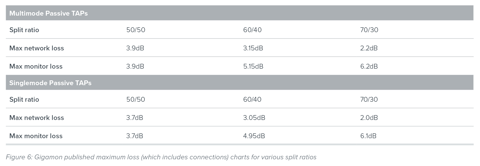
Regardless of the method used, the passive splitter physically diverts a portion of the light from its original source. The proportional share of light for each path is known as the split ration. The split ratio is written as a combination of two percentages. The first number is designated as the network percentage, the second number is the monitor percentage. They always add up to 100 percent. For example, a common split ratio for traditional 1Gb short-range links is 70/30; where seventy percent of the light continues to the network and thirty percent is allocated to the monitor port.
The concept is to allocate more light to the network to reduce the risk of dropping network traffic. Speeds such as 10Gb, 40Gb and 100Gb have different technical requirements and tend to use more of an even split ratio such as 50/50 or 60/40. The most common split ratio deployed in networks today tends to be 50/50, provided the proper light levels are available. When light levels are marginal, the safe option is to move to better optics offering higher safety margins.
Gigamon tests every TAP manufactured and provides the actual tested loss values with each Gigamon-branded TAP shipped. In addition, Gigamon data sheets for TAPs describe the maximum acceptable network and monitor loss values (including connections) for each split ratio are as follows:
Optical Speeds and Types
Fiber TAPs are available for a wide variety of speeds and cable types. Most networks rely on IEEE 802.x standard-based optical cables. Speed is shown in gigabits per second or Gbps. However, it is commonly shortened to Gb or G. The most common speeds in use today are 1Gb, 10Gb and 40Gb, but the trend is quickly moving toward higher speed networks of 100Gb. Speeds of 400Gb are on the horizon, and expected to be available in the next few years. Since different transceiver technologies are leveraged for each speed, passive fiber TAPs do not change speeds midstream. If traffic is coming in at 10Gb with a wavelength of 1550nm, the traffic after the split has the same speed and wavelength.
For best results, cable types should be consistent across the flow. Match the cables to the need. In general, there are two major categories of fiber cable:
- Multimode
- Singlemode
Shorter distance links often run over multimode cable, while longer distance connections tend to use singlemode cable. The main difference between the two is multimode has a larger core diameter (up to 62.5μm), which allows for a broader dispersion of light. This permits lower-cost, LED-based optical transmitters to be used, keeping the overall cost down.
Since the light is dispersed across multiple modes on a larger core, the light has a tendency to bounce around a lot while it is traveling through the cable. Since different modes travel different lengths, the signals arrive at different times, making it difficult to distinguish one pulse from another. This leads to higher attenuation, or loss of signal, as the light travels down its path. Because of this, multimode is only rated for shorter runs of up to a couple hundred meters, depending on the cable type. It should be noted that the larger, core multimode cabling (62.5μm) should only be used for 1Gb and below.
 Figure 7: Multimode and singlemode cables
Singlemode fiber runs at higher bandwidths over smaller cores. This requires higher precision instrumentation and higher priced laser diodes to transmit the signal. Vertical-Cavity Surface-Emitting Lasers (VCSELs) are small flat emitters commonly used for short and medium distances. Longer distances such as 40km and beyond require more precise (and higher-temperature) Fabry-Perot lasers. Figure 8 depicts common cable types.
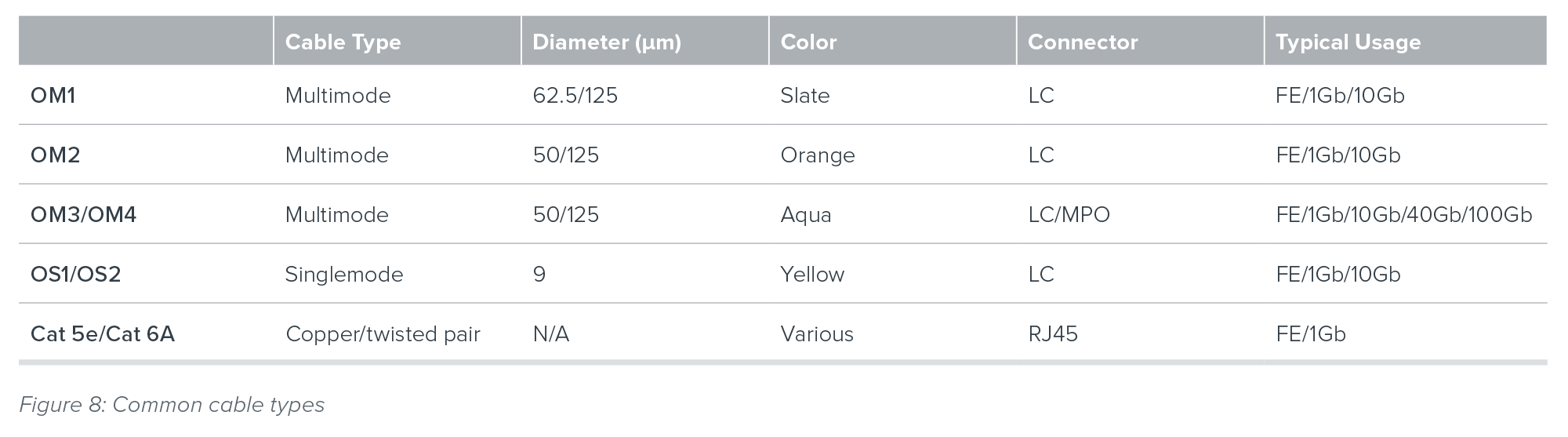
 Figure 9: Theoretical loss chart
The above chart shows the assumed loss associated between two endpoints with a transmitter at one end and a receiver at the other with two connectors (at each end). The following formulas may be used:
Power Budget = Transmitter Power – Receiver Sensitivity = a – e
Cable Attenuation = Decrease in signal strength due to absorption and scattering per kilometer of a given cable type = b – c
Connection Loss = Signal degradation due to connectors in the system = (a - b) + (c - d)
Total Cable Plant Loss = Cable Attenuation + Connection loss = (a – b) + (b – c) + (c – d)
Power Margin = Additional power that could be consumed while still providing a valuable signal = Power Budget – Total Cable Plant Loss
Whenever possible, it is best to run the calculations using the actual numbers from the transceivers and cables in use. An alternative method is to take the worst-case scenario and plug in the minimum numbers as established in the IEEE specifications. If we were to pull numbers for a 10 meter run of OM2 multimode fiber running 1Gb (according to IEEE 802.3-2012 section 3 specifications) we would find:
1000BASE-SX Transceiver Average Launch Power (Min) = -9.5dBm
1000BASE-SX Receiver Sensitivity = -17dBM
Attenuation rates of multimode cable (for 10 meters) = 3.5dB/Km = .035dB/10m
Connection loss of multimode connectors = .5dB
Plugging in the worst-case numbers into the original equations, we would come to the following conclusions:
Power Budget = (-9.5) – (-17) = 7.5dBm
Cable Attenuation (10 meters) = 3.5/100 = .035dB
Connection loss = .5 x 2 connectors = 1dB
Total Cable Plant Loss = Cable attenuation + Connection loss = .035 + 1 = 1.035
Power Margin = 7.5 – 1.035 = 6.465
Thus with a Power Margin of 6.465 dB, a TAP will fit nicely into this network. The TAP with the highest Maximum Loss in Figure 6 is 6.2 db (including connections to the TAP). So there is ample margin to insert a 50/50, 60/40, or 70/30 split ratio TAP into this environment.
However, the user should be aware that all environments are different. The 1Gb example shown above provides for a much larger margin than higher-speed optics such as 10Gb, 40Gb and 100Gb. As an example, the entire power budget allocated for some short-range 40Gb transceivers is less than 2 dBm. Best practices dictates running the numbers for each installation. As a general rule, Gigamon does not recommend using a 70/30 split ratio for 10Gb multimode infrastructures as the light margins are too low for the monitored traffic.
To quickly summarize light calculations determining passive TAP placements, there are four primary considerations that come into play:
- Transmit power (the starting light signal)
- Receiver sensitivity (residual light seen at the other end)
- Light loss within the cable plant (prior to TAP insertion)
- Impact of the TAP (the actual TAP signal loss)
Active TAPs
Active TAPs are not passive. They require their own power source to regenerate the signals. There is no split ratio consideration because the TAP receives the message and then retransmits it to both the network and monitoring destinations. From a highlevel perspective this would appear to be a positive feature. Even so, passive TAPs are preferred. During a power outage, an active TAP cannot regenerate the signal, so it becomes a point of failure. Since a passive TAP is not powered, it would be unaffected during a power outage and the packets (originating from a source that still has power) would continue to flow.
When are active TAPs preferred? Active TAPs are commonly used for the following applications where passive TAPs are not a good alternative:
- Locations where the light levels are too low to use a splitter → regeneration provides a viable solution
- Copper infrastructures → where electricity is used to move electrons (instead of photons)
- Signal conversions → since an active TAP regenerates the signal anyway, it can also be designed to create a signal of a different type (such as 10Gb SR converted to 10Gb LR)
- SFP-based links that cannot otherwise be broken (such as TwinAX cabling) → regeneration works here as well
As long as the drawbacks of power failure are fully understood, active TAPs provide excellent value and extend visibility to sections of the network that would otherwise go unmonitored. Sophisticated active TAPs offer battery backup to extend usage during power failures. When the battery begins to die, some TAPs will offer additional failover capabilities. For example, when certain active copper TAPs lose power, electromagnetic relays fall into place to physically close a link to allow traffic to continue flowing through the network. The monitoring traffic stops, but at least the network traffic is protected.

TAP Best Practices
- A TAP is a basic building block of any visibility system. For complete coverage, many companies have adopted a TAP-ALL strategy as a best practice. This means that all critical links are set up with TAPs (and/or SPANs), even if the traffic is not under continuous monitoring. By having the TAP already in place, in the event of a security breach or troubleshooting requirement, the data is readily accessible.
- The best time to deploy a TAP is when the infrastructure is being built, as it is always more costly to introduce equipment after the fact. A TAP installation requires bringing down a network link, so should be done during a scheduled maintenance window.
- TAPs are generally preferred over SPAN ports, yet both provide value. Best practices dictate deploying physical TAPs for critical links with medium to high utilization. SPANs are best used in locations that are not conducive to TAPs. Examples include links with power budget limitations and remote sites with low-utilization links.
- Traditionally, if both options were available, passive TAPs were generally preferred over active TAPs. The primary reason for this was to minimize loss during power outages. This trend, however, is changing. Not only do active TAPs boost the signal to provide longer distances, but many now include battery backups to minimize power loss and provide fail-safe operation.
- Fully understand the light limitations of your environment prior to making any infrastructure change. They are also used to determine the appropriate split ratios to deploy. It is always best to use the sensitivity and power ratings of the specific optics in use. When actual vendor-based light numbers are unavailable, worst case numbers may be calculated as per IEEE specifications. If the power budget is too narrow, consider using an active TAP or SPAN port. Another option is to upgrade the optics and cabling to a standard rated for longer distances.
- Most TAP failures are due to improper cabling. When connecting TAPs, always use new cabling and properly clean all connections. Never mix and match cable types within a single, end-to-end link. Match each TAP to the cable type in use and never bend cabling beyond specifications. For newer technologies, such as Cisco BiDi deployments, only use TAPs that are rated for the exact wavelengths in use.
Although a TAP can be connected directly to a monitoring tool, it is far better to connect directly to the Gigamon Deep Observability Pipeline.
Summary
A TAP represents the connection point where real traffic is copied directly from the network. As such, it is the first step toward any visibility solution. TAPs can be standalone devices or integrated directly as a module inside a visibility node. In both cases, traffic is copied for monitoring, security and analysis as the traffic continues to pass through the network unimpeded.
For more information or to download the full PDF, please click here.